Product Description
1.Product Description
Forging—Normalizing&Tempering—Rough machining—Hardening Tempering—Semi-finishing machining—Drilling deep hole—Hobbing—Tooth Surface Quenching—Grinding Shaft diameter—Gear grinding—Inspection—Package—Delivery
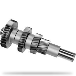
We’re manufacturer of Bevel/Helical/Spur/Internal Gear, Bevel/Spiral/Crown Pinion, Gear Segment/Helical Rack, Herringbone/Helical Gear Shaft/Eccentric Shaft/ Hollow Shaft/ Crank shaft/Camshaft, Abnormal Axle and other transmission parts for transmission device & equipment (large industrial reducer & driver),which mainly used on cement, mining, metallurgical industry, Seaport facilities etc.
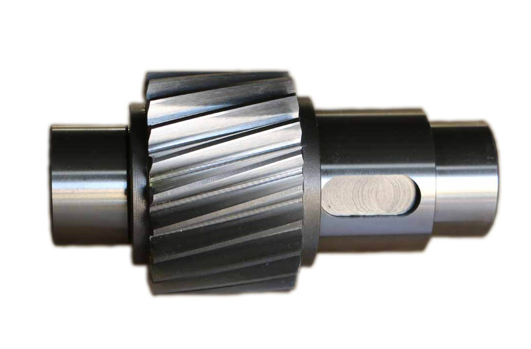
1.1. Processing Grinded CHINAMFG Pinion Shaft, CHINAMFG Gear Set
Gear Shaft drawing CHECK, Make Forging Mold, Forging Mold Quality Inspection Check, Machine Processing, Check Size\Hardness\Surface Finish and other technical parameters on drawing.
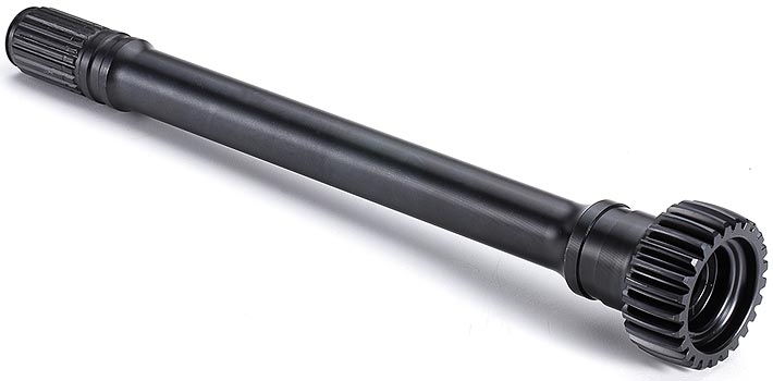
1.2. Herringbone Gear Shaft Package
Spray anti-rust oil on Herringbone Gear Shaft, Wrap waterproof cloth around Gear Shaft for reducer, Prepare package by shaft shape&weight to choose steel frame, steel support or wooden box etc.
1.3. OEM Customized Grinded double helical gear shaft
We supply OEM SERVICE, customized herringbone gear shaft with big module, more than 1tons big weight, more than 3m length, 42CrMo/35CrMo or your specified required material double helical gear shaft.
2.Product Technical info.
| Module | m | Range: 5~70 |
| Gear Teeth Number | z | OEM by drawing’s technical parameters |
| Teeth Height | H | OEM by drawing’s technical parameters |
| Teeth Thickness | S | OEM by drawing’s technical parameters |
| Tooth pitch | P | OEM by drawing’s technical parameters |
| Tooth addendum | Ha | OEM by drawing’s technical parameters |
| Tooth dedendum | Hf | OEM by drawing’s technical parameters |
| Working height | h’ | OEM by drawing’s technical parameters |
| Bottom clearance | C | OEM by drawing’s technical parameters |
| Pressure Angle | α | OEM by drawing’s technical parameters |
| Helix Angle, | OEM by drawing’s technical parameters | |
| Surface hardness | HRC | Range: HRC 50~HRC63(Quenching) |
| Hardness: | HB | Range: HB150~HB280; Hardening Tempering/ Hardened Tooth Surface |
| Surface finish | Range: Ra1.6~Ra3.2 | |
| Tooth surface roughness | Ra | Range: ≥0.4 |
| Gear Accuracy Grade | Grade Range: 5-6-7-8-9 (ISO 1328) | |
| Length | L | Range: 0.8m~10m |
| Weight | Kg | Range: Min. 100kg~Max. 80tons Single Piece |
| Gear Position | Internal/External Gear | |
| Toothed Portion Shape | Spur Gear/Bevel/Spiral/Helical/Straight | |
| Shaft shape | Herringbone Gear Shaft / Gear Shaft / Eccentric Shaft / Spur Gear / Girth Gear / Gear Wheel | |
| Material | Forging/ Casting |
Forging/ Casting 45/42CrMo/40Cr or OEM |
| Manufacturing Method | Cut Gear | |
| Gear Teeth Milling | √ | |
| Gear Teeth Grinding | √ | |
| Heat Treatment | Quenching /Carburizing | |
| Sand Blasting | Null | |
| Testing | UT\MT | |
| Trademark | TOTEM/OEM | |
| Application | Gearbox, Reducer, Petroleum,Cement,Mining,Metallurgy etc. Wind driven generator,vertical mill reducer,oil rig helical gear,petroleum slurry pump gear shaft |
|
| Transport Package | Export package (wooden box, steel frame etc.) | |
| Origin | China | |
| HS Code | 8483409000 |
Material Comparison List
| STEEL CODE GRADES COMPARISON | |||||
| CHINA/GB | ISO | ГΟСТ | ASTM | JIS | DIN |
| 45 | C45E4 | 45 | 1045 | S45C | CK45 |
| 40Cr | 41Cr4 | 40X | 5140 | SCr440 | 41Cr4 |
| 20CrMo | 18CrMo4 | 20ХМ | 4118 | SCM22 | 25CrMo4 |
| 42CrMo | 42CrMo4 | 38XM | 4140 | SCM440 | 42CrMo4 |
| 20CrMnTi | 18XГT | SMK22 | |||
| 20Cr2Ni4 | 20X2H4A | ||||
| 20CrNiMo | 20CrNiMo2 | 20XHM | 8720 | SNCM220 | 21NiCrMo2 |
| 40CrNiMoA | 40XH2MA/ 40XHMA |
4340 | SNCM439 | 40NiCrMo6/ 36NiCrMo4 |
|
| 20CrNi2Mo | 20NiCrMo7 | 20XH2MA | 4320 | SNCM420 | |
3.Totem Service
TOTEM Machinery focus on supplying GEAR SHAFT, ECCENTRIC SHAFT, HERRINGBONE GEAR, BEVEL GEAR, INTERNAL GEAR and other parts for transmission devices & equipments(large industrial reducers & drivers). Which were mainly used in the fields of port facilities, cement, mining, metallurgical industry etc. We invested in several machine processing factories,forging factories and casting factories,relies on these strong reliable and high-quality supplier network, to let our customers worry free.
TOTEM Philosophy: Quality-No.1, Integrity- No.1, Service- No.1
24hrs Salesman on-line, guarantee quick and positive feedback. Experienced and Professional Forwarder Guarantee Log. transportation.
4.About TOTEM
1. Workshop & Processing Strength
2. Testing Facilities
3. Customer Inspection & Shipping
5. Contact Us
ZheJiang CHINAMFG Machinery Co.,Ltd
Facebook: ZheJiang Totem
| Material: | Alloy Steel |
|---|---|
| Load: | Drive Shaft |
| Stiffness & Flexibility: | Forging |
| Journal Diameter Dimensional Accuracy: | It5-It9 |
| Axis Shape: | Straight Shaft |
| Shaft Shape: | Customized |
| Customization: |
Available
| Customized Request |
|---|
What are the safety considerations when working with gear shafts?
Working with gear shafts involves potential hazards that need to be considered to ensure the safety of individuals involved. Proper safety measures should be followed to prevent accidents and injuries. Let’s explore some important safety considerations when working with gear shafts:
- Personal Protective Equipment (PPE):
Wearing appropriate personal protective equipment is essential when working with gear shafts. This may include safety glasses or goggles to protect the eyes from flying debris, gloves to provide hand protection, and appropriate footwear to prevent foot injuries. PPE should be selected based on the specific hazards associated with the task.
- Machine Guarding:
Ensure that gear shafts and related machinery are properly guarded. Machine guards help prevent accidental contact with moving parts and reduce the risk of entanglement or entrapment. Guards should be in place and functioning correctly before any work is performed on or near gear shafts.
- Lockout/Tagout Procedures:
Prior to working on gear shafts, it is important to follow lockout/tagout procedures. These procedures involve isolating the machinery from its power source and ensuring that it cannot be energized accidentally. Lockout/tagout procedures help protect workers from unexpected startup or release of stored energy, minimizing the risk of injury.
- Proper Training and Knowledge:
Workers should receive proper training on the safe operation and maintenance of gear shafts. They should be familiar with the potential hazards, safety procedures, and emergency protocols. Training should cover topics such as safe handling, proper use of tools, and awareness of potential risks associated with gear shafts.
- Risk Assessment:
Conduct a thorough risk assessment before performing any work involving gear shafts. Identify potential hazards, assess the associated risks, and implement appropriate control measures. This may include evaluating the stability of the work area, assessing the need for additional support or lifting equipment, and identifying any potential pinch points or crush hazards.
- Proper Lifting Techniques:
When handling or moving gear shafts, use proper lifting techniques to prevent strain or injury. Avoid lifting heavy loads manually when possible and use mechanical lifting aids or equipment when necessary. Ensure that lifting equipment is in good working condition, properly rated for the load, and operated by trained personnel.
- Clean and Organized Work Area:
Maintain a clean and organized work area around gear shafts. Remove any unnecessary items or debris that could pose a tripping or slipping hazard. Keep tools and equipment properly stored when not in use to prevent accidents and injuries.
- Regular Maintenance and Inspection:
Perform regular maintenance and inspection of gear shafts to ensure their safe operation. Check for signs of wear, damage, or misalignment. Address any issues promptly and follow manufacturer’s guidelines for maintenance intervals and procedures. Regular inspections help identify potential safety concerns and prevent equipment failure.
- Communication and Collaboration:
Encourage effective communication and collaboration among team members when working with gear shafts. Clear communication ensures that everyone is aware of their roles and responsibilities and can alert others to potential hazards or unsafe conditions. Collaboration promotes a safety culture and allows for the sharing of knowledge and best practices.
By considering these safety measures when working with gear shafts, the risk of accidents and injuries can be significantly reduced. It is important to prioritize safety and create a work environment where individuals are informed, trained, and equipped to work safely with gear shafts.
What are the factors to consider when designing gear shafts for specific applications?
Designing gear shafts for specific applications requires careful consideration of various factors to ensure optimal performance and reliability. Let’s explore the key factors that should be taken into account during the design process:
- Load and Torque Requirements:
The load and torque requirements of the specific application are crucial considerations. Understanding the maximum load the gear shaft will experience and the torque it needs to transmit is essential for selecting appropriate materials, determining the required dimensions, and ensuring the gear shaft can handle the anticipated forces effectively.
- Gear Type and Configuration:
The gear type and configuration directly influence the design of the gear shaft. Different gear types, such as spur gears, helical gears, bevel gears, or worm gears, have unique characteristics that impact the design considerations for the gear shaft. Factors such as gear tooth profile, pitch, pressure angle, and gear ratio need to be taken into account during the design process to ensure proper alignment, engagement, and efficient power transmission.
- Material Selection:
Selecting the appropriate material for the gear shaft is crucial for its strength, durability, and performance. Factors such as the required strength, wear resistance, fatigue resistance, and corrosion resistance should be considered when choosing the material. Common materials for gear shafts include various steels, alloys, and sometimes specialized materials like bronze or brass, depending on the specific application requirements.
- Shaft Dimensions and Geometry:
The dimensions and geometry of the gear shaft need to be carefully determined. Factors such as shaft diameter, length, keyways, chamfers, and fillets are important considerations. Proper shaft dimensions and geometry ensure sufficient strength, proper fit within the gear assembly, and compatibility with other components within the system.
- Bearing Support and Lubrication:
The gear shaft design should incorporate provisions for bearing support and lubrication. Bearings placed along the gear shaft help reduce friction, support the shaft under load, and ensure smooth rotation. Adequate lubrication, such as oil or grease, is necessary to minimize wear between the gear shaft and bearings, as well as to reduce heat generation and promote efficient operation.
- Heat Treatment and Surface Finish:
Depending on the application requirements, heat treatment processes like quenching and tempering may be applied to enhance the mechanical properties of the gear shaft. Heat treatment can improve hardness, strength, and toughness, increasing the gear shaft’s ability to withstand high loads and resist wear. Additionally, considering the surface finish of the gear shaft can help reduce friction, improve gear meshing, and minimize the risk of surface damage.
- Manufacturability and Cost:
Designing gear shafts should also take into account manufacturability and cost considerations. The design should be feasible for manufacturing processes such as machining, forging, or casting, depending on the chosen material and complexity of the design. The design should also aim to optimize material usage and minimize manufacturing costs while meeting the required performance criteria.
In summary, when designing gear shafts for specific applications, factors such as load and torque requirements, gear type and configuration, material selection, shaft dimensions and geometry, bearing support and lubrication, heat treatment and surface finish, as well as manufacturability and cost considerations, should all be carefully evaluated. By considering these factors, a well-designed gear shaft can be developed to meet the specific needs of the application, ensuring reliable and efficient power transmission within the gear system.
How do gear shafts differ from other components in gear mechanisms?
Gear shafts have distinct characteristics that differentiate them from other components in gear mechanisms. Here are some key differences between gear shafts and other components:
- Function:
Gear shafts serve as the mechanical linkages that connect and transmit rotational motion between gears. Their primary function is to transfer power and torque from one gear to another, enabling the desired mechanical output. Other components in gear mechanisms, such as gears themselves, may have different functions, such as meshing with other gears, providing different gear ratios, or changing the direction of motion.
- Structure and Design:
Gear shafts typically have a cylindrical or rod-like structure with a smooth surface. They are designed to provide support, alignment, and rotational movement for the connected gears. In contrast, other components, such as gears, may have complex tooth profiles, specific shapes, or specialized features to achieve their intended functions, such as transmitting motion, altering speed, or multiplying torque.
- Location and Mounting:
Gear shafts are often positioned centrally within gear mechanisms and are mounted on bearings or bushings. This central location allows them to connect with multiple gears and efficiently transmit power. Other components, such as gears, may be positioned at different locations within the mechanism, depending on their specific roles and interactions with other gears.
- Rotational Movement:
Gear shafts primarily rotate within the gear mechanism, transmitting the rotational motion from one gear to another. They are designed to withstand the torque and rotational forces applied during operation. In contrast, other components, such as gears, may have different types of movement or interactions, such as meshing with other gears, sliding, or engaging and disengaging with additional mechanisms or clutches.
- Size and Dimension:
Gear shafts can vary in size and dimension depending on the specific application and gear mechanism requirements. They need to be designed to handle the load, torque, and speed demands of the system. Other components, such as gears, may also come in various sizes, but their shape, tooth profiles, and dimensions are tailored to achieve specific gear ratios, rotational speeds, or torque multiplication.
- Material Selection:
Gear shafts are commonly made from strong and durable materials, such as steel or alloy metals, to withstand the forces and stresses encountered during operation. The material selection for gear shafts prioritizes strength, wear resistance, and fatigue resistance. Other components, such as gears, may have different material requirements based on their specific functions, such as hardness, friction properties, or heat dissipation.
In summary, gear shafts differ from other components in gear mechanisms in terms of their function, structure, location, movement, size, and material selection. Gear shafts primarily serve to transmit power and torque between gears, providing support, alignment, and rotational movement. Understanding these differences is crucial for designing and assembling efficient and reliable gear mechanisms.


editor by CX 2023-09-18